
These trophy die casting design guidelines translate general design for die casting awards into trophy geometry, finish planning, and project control. For procurement managers, industrial designers, and technical buyers, the key question is not whether a trophy can be made metal, but whether it can be released from the tool, filled cleanly, finished consistently, assembled logically, and packed without avoidable risk. Me Trophy supports that conversation as a custom trophy manufacturer and project partner, and its metal casting capabilities are most useful when the design brief, CAD model, and finish intent are reviewed together.
Detailed awards can often be produced as die-cast metal trophies when the body has stable mass, controlled relief, and a parting strategy that can be concealed. Zinc alloy is often considered for detailed bodies, while copper-based programs may also be explored when the visual brief calls for it; the final choice must be confirmed against the project geometry, finish stack, and tooling approach. If the design depends on deep reverse pockets, ultra-thin fins, or an oversized hollow form, the drawing may need simplification or a hybrid build before tooling is released. For a product-level overview, see die-cast metal trophies.
1. When Die Casting Fits a Trophy Design
A practical process-fit review starts with three questions: can the trophy be split cleanly, can the detail survive casting and finishing, and can the base and body be assembled without exposing process marks? If the answer is yes on most of the visible geometry, the project is usually worth moving forward into formal design evaluation. If the answer is uncertain, the drawing should be reviewed before tooling rather than after the first sample.
Use the following signals as a quick decision aid.
| Geometry question | Usually favorable sign | Redesign signal |
|---|---|---|
| Overall shape | Clear silhouette with accessible surfaces | Very deep cavities or reverse folds |
| Detail level | Readable relief that does not depend on knife-edge features | Extremely fine fins or micro-text |
| Mass distribution | Balanced body and base with gradual transitions | Large hidden mass or heavy local thickening |
| Assembly logic | Few joins and obvious locating features | Complex stacking of cast, machined, and decorative parts |
Die casting is usually most practical when the trophy face, side surfaces, and base can all be described in a way the tool can open and close without trapping the part. A one-piece award body may be feasible when the geometry is clean and the decorative language is broad. A more sculptural trophy may still be possible if the design is relaxed in a few hidden areas, such as the rear face, underside of the base, or internal transitions that the viewer will not inspect closely.
By contrast, the following shapes often need an earlier feasibility review: very deep undercuts behind figurative elements, extremely thin openwork that behaves like a fin, large hollow volumes that would need complicated cores, and reverse features that would force the tool to move in more than one direction. If the design team is still deciding between cast-in detail and added decorative elements, Me Trophy can help separate what belongs in the casting from what should be added later in assembly or finishing.
If the concept is still changing, that is the right time to request an internal design evaluation rather than waiting for quote-stage surprises. A short review of CAD, section views, and intended finish usually saves more time than revising the tool after the first sample.
2. Parting Lines, Draft, and Ejection Planning
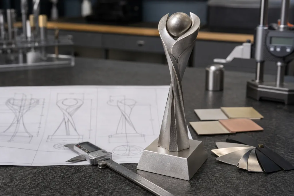
Parting line planning is one of the most important trophy die casting design guidelines because it determines where the tool opens, where visible seams appear, and where surface finishing effort is concentrated. The safest location is usually a concealed edge, a base seam, a rear transition, or another low-visibility zone that does not compete with the award face. On a trophy, the parting line should be treated as part of the composition, not as an afterthought.
For a die casting draft angle trophy, draft should be planned as a release strategy and a finish-protection strategy at the same time. Draft that is too aggressive may distort the intended silhouette; draft that is too slight may risk scuffing, sticking, or cosmetic damage during ejection. The final draft decision must be confirmed per project because it depends on alloy, surface texture, tool layout, and whether the face will be polished, plated, painted, or patinated.
For die-casting-specific tolerances, draft guidance, and drawing control, a useful technical reference is the NADCA Product Specifications Standards for Die Castings. Buyers should use those standards together with the actual part geometry and finish stack, then confirm the project limits with the manufacturer before approval.
Ejection planning also needs to be visible in the CAD review. Ejector marks, gates, runners, and overflow locations should be hidden where possible, especially on award faces or polished emblem areas. If the design leaves no hidden zone, the geometry usually needs to be adjusted so the process marks fall on a less prominent surface. In many trophy programs, the rear face or underside of the base is the best place to absorb these unavoidable tool marks.
When the split line or ejection path is still uncertain, the issue often belongs in tooling strategy rather than in final decoration. That is why Me Trophy treats the first review as a process-fit discussion tied to mold development, not just as a visual approval step.
For programs where the split and release strategy need to be mapped out early, the next practical step is mold development. That stage should lock the parting concept before the design becomes dependent on cosmetic assumptions.
3. Wall Thickness, Ribs, Bosses, and Weight Control
Die cast trophy wall thickness should stay as uniform as the design allows. Uniform sections support more predictable filling, more even cooling, and a cleaner external appearance. When wall thickness changes abruptly, the result may be visible distortion, inconsistent surface texture, or a local area that behaves differently during polishing or plating. For a detailed award, those defects are often more noticeable than they are on a purely functional product.
That does not mean a trophy must be flat or featureless. Ribs and light structural bosses can add stiffness without making the body look heavy. The rule is to use structure to support the form, not to build hidden mass that later telegraphs through the finish. A rib should help the part keep its shape; it should not create an isolated thick zone that changes the visual rhythm of the trophy.
Weight control matters for three practical reasons. First, the award has to feel stable in the hand when it is presented or displayed. Second, the base attachment must support the center of gravity without making assembly awkward. Third, shipping and packaging should be planned around the real part weight, not an optimistic estimate from the concept rendering. Exact weight targets, balance points, and attachment choices are project-specific and must be confirmed with the final CAD and package plan.
| Design area | Good practice | Risk if ignored |
|---|---|---|
| Body shell | Keep mass changes gradual | Warpage or visible finish change |
| Ribs | Use ribs for stiffness and shape support | Localized thick zones and distortion |
| Bosses and mounts | Plan them with assembly access in mind | Poor fit, hidden stress, difficult fastening |
| Base | Balance presentation, stability, and shipment | Tipping risk or overbuilt packaging |
When the trophy includes a pedestal, name plate, or joined figure, the weight of each sub-component should be considered together. A light upper body on a heavy base may feel secure but can also create awkward assembly or visual imbalance. A heavier body may need a broader base footprint or a different attachment strategy. None of these choices should be assumed; they must be confirmed as part of the design review.
4. Undercuts, Inserts, Holes, and Secondary Operations
Metal trophy undercut design should be reviewed case by case. Some undercuts are acceptable if the tooling can move cleanly around them, but others quickly multiply tool complexity. If the trophy includes undercuts or internal recesses, the tool may need slides or cores; retracting them after solidification helps release the part and control flash. An industry reference from NADCA shows how movable features can support complex internal geometry in die casting: Slides for Internal Features.
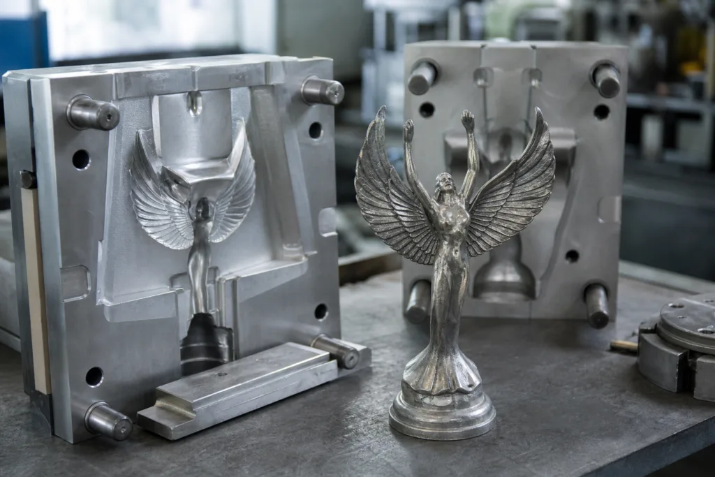
For buyers, the core decision is whether a feature should be cast directly or created later. A hole that is central to the visual design may be cast if the geometry and release direction allow it. A tight slot, a small thread, or a precision mounting point is often better treated as a secondary operation, such as drilling, tapping, machining, or an inserted fastener feature. The logic is simple: every feature that is moved into the tool increases tooling complexity, while every feature that is removed from the tool increases post-cast work.
A formal design evaluation should compare those two costs together instead of looking at tool cost alone. Sometimes a slightly simpler casting leads to a more reliable and repeatable trophy. In other cases, a controlled tooling feature saves enough assembly time to justify the added mold complexity. The right answer depends on the whole project, not on any single drawing line.
In trophy work, inserts can also be useful when a decorative element needs a different material, a hidden fastening point, or a local wear surface. The challenge is to keep the insert logic understandable during assembly and invisible in the finished award. If the team cannot explain where the part is located, how it is retained, and how it is inspected, the feature is probably too complex for the program.
- Cast directly when the feature is broad, visible, and naturally aligned with the tool opening direction.
- Machine after casting when the feature needs better positional control or cleaner edges.
- Use inserts when the feature needs a separate material, hidden fastening, or repeatable assembly location.
- Redesign the geometry when the feature creates deep reverse locking, awkward release, or unnecessary flash risk.
5. Relief Detail, Text, Logos, and Surface Expectations
Relief detail is where many detailed metal trophies succeed or fail. Raised text, engraved text, iconography, and small logos can all be cast, but only if the visual language fits the process. The important issue is not whether a line can exist in the CAD file; it is whether the line will still read clearly after casting, polishing, plating, painting, or patina work. Small marks that look sharp on screen can disappear after finishing if the geometry is too tight.
For logo and text design, think in terms of readability first and decoration second. If a logo is intended to be read from a distance, it should be scaled and placed so the major strokes are stable and the background is not fighting the message. If the logo is very small, a laser mark, a machined mark, a decal, or another post-cast method may preserve clarity better than forcing the feature into the casting. The best choice depends on the brand brief, the alloy, and the selected finish.
Surface expectations should also be aligned early. A polished award face will reflect tooling marks differently from a textured or patinated surface. Plating may emphasize edges and transitions, while paint may make small geometry more forgiving but can hide extremely fine relief. That means the CAD should define not just the shape, but the finish zones that belong to each area of the trophy.
A useful rule is to separate the trophy into visible hero surfaces and technical support surfaces. Hero surfaces deserve the cleanest draft transitions, the least visible parting line, and the most controlled relief. Support surfaces can absorb gates, ejectors, and assembly features if that makes the whole piece more manufacturable. This is often the difference between a design that looks premium in renderings and a design that remains premium after production.
For trophy projects, the finish stack should always be confirmed alongside the geometry. A polished, plated, painted, or patinated award may all use the same cast body, but each finish reacts differently to edge sharpness, texture, and seam location. That is why finish approval should never be separated from the castability review.
6. DFM Review and Sample-Validation Sequence

The best buyer workflow is straightforward: submit CAD, mark the visible and hidden surfaces, review castability, confirm tooling logic, approve a sample, then release final production. This sequence helps ensure that trophy casting tolerance, assembly logic, and finish zones are confirmed before the project becomes expensive to revise. It also makes it easier for procurement teams to compare design risk across multiple concepts.
Me Trophy’s role in that workflow is to support the project from concept clarification through tooling and validation. After the design review, the next engineering question is whether the mold layout can be built to support the parting concept and any required slides, cores, or inserts. If the design is accepted, mold development becomes the bridge between CAD intent and a real castable tool.
Before tooling commit, a feasibility review should be used as the gate. That review should confirm the tolerance stack, the assembly logic, the visible seam location, the finish zones, and the packaging assumptions. If any of those items are still unknown, the project should stay in review rather than moving blindly into production.
| DFM check area | What to confirm | Why it matters |
|---|---|---|
| Tolerance stack | Which dimensions are critical and which are visual only | Prevents over-specifying cast features |
| Assembly logic | How parts locate, fasten, and hide seams | Avoids rework and visible gaps |
| Finish zones | Where polishing, plating, paint, or patina must stay clean | Protects the premium face of the award |
| Packaging assumptions | How the award will be protected in transit | Reduces handling damage and final shipping surprises |
Once the first sample is available, it should be checked against the drawing, the finish sample, and the real assembly sequence. This is where sample production earns its value: it exposes issues that are hard to see on screen, such as edge softness, visible seams, and handling balance. After that, the sign-off should be tied to documented quality control checkpoints so the approved sample becomes the production reference.
If the concept is still uncertain, return to Me Trophy’s metal casting capabilities review before tooling is approved. That is the right commercial decision when the team needs to choose between simplification, secondary operations, or a full custom cast solution.
Frequently asked questions
Can every detailed metal trophy be die cast?
No. Die casting works best when the body can be split cleanly, the detail depth is practical for the alloy and tool, and the geometry does not depend on hidden reverse forms. Deep undercuts, ultra-thin fins, and oversized hollow shells often need redesign or a hybrid build.
Where should a parting line go on a trophy?
Place it on a concealed edge, a base seam, or another low-visibility transition so the line does not compete with the award face. The final location should also protect plating, polishing, and assembly access.
What should happen with wall thickness changes?
Keep walls as uniform as possible and use smooth transitions instead of sudden mass changes. If stiffness is needed, add ribs or structure rather than large local thickness jumps.
Can holes, slots, and undercuts be cast directly?
Some can, but not all. Small holes may be formed with the tool, while threads, tight slots, and reverse geometry often work better as drilled, tapped, machined, or inserted features. Each metal trophy undercut design should be reviewed case by case.
Why request samples before production release?
Samples confirm that the casting fills correctly, the finish reads as intended, and the assembly, tolerance, and packaging assumptions still work together. A sample is the safest point to catch design issues before tooling is locked.