
When a trophy project moves from concept to production, the quality of the files you send often decides how fast engineering can confirm feasibility, how accurate the quotation will be, and whether tooling can begin without avoidable rework. For a custom project, the factory is not only checking what the design looks like; it is checking whether the artwork can be made as a stable metal product, whether the assembly logic is clear, and whether the finish plan can survive real production conditions. If you are still shaping the brief, the custom trophy design process helps align the creative intent with manufacturing constraints early.
This guide explains the practical custom trophy design file requirements for brand designers, product developers, and procurement teams. It separates what the factory needs at concept, quote, and tooling stages; shows how to prepare a trophy artwork file format and a trophy CAD file; and highlights the most common file risks that slow down custom award artwork preparation.
What the Factory Needs at Concept, Quote, and Tooling Stages
Not every project needs a fully finished CAD package on day one. The right handoff depends on how far the design has developed and what the production team must confirm. A concept sketch may be enough for an early feasibility discussion, while tooling cannot start until dimensions, geometry, and finish decisions are clear.
If your team wants an early production read before investing in final artwork, a formal design evaluation is often the fastest way to identify missing data, likely manufacturing risks, and any places where the concept needs to be rebuilt for the factory process.
| Project stage | What to send | What the factory checks | Common risk if missing |
|---|---|---|---|
| Concept | Sketches, reference images, logo files, rough size target, event or brand context | Visual direction, production route, general structure | Unclear scope and repeated redesign |
| Quote | Dimensioned artwork, material intent, finish notes, personalization count, packaging expectations | Process steps, complexity, likely tooling path | Quote based on assumptions instead of real inputs |
| Tooling | Approved vectors, dimensioned drawing, 3D model or controlled sections, revision history, variable data | Feasibility, part split, mold strategy, assembly logic | Delay, rework, or tool changes after approval |
At the concept stage, the factory usually needs the intent: event type, target size range, brand style, expected finish, personalization count, and reference images. At the quote stage, it needs enough structure to estimate process steps such as mold development, casting, polishing, painting, plating, assembly, and packing. At the tooling stage, it needs approved geometry, revision-controlled artwork, and all variable data locked for production.
Vector Logos, Fonts, Colors, and Brand References

For logo work, vector files are the safest starting point. They preserve edges, scale cleanly, and are easier to revise for engraving, relief, etching, or printed inserts. A vector logo for trophy production is usually preferable in AI, EPS, SVG, or PDF form when the artwork is truly vector. Raster files such as JPG or PNG can still help as references, but they often need rebuild if the factory must trace a crisp edge or isolate a logo for tooling.
The University of Texas at Austin’s Artwork Specifications also notes the production advantages of vector artwork, careful color handling, and proper font submission. That guidance translates well to custom trophy work: if the design includes printed nameplates, logo plaques, or packaging graphics, prepare color references in the correct mode for the production step, and confirm whether spot colors will be matched, converted, or simplified.
Fonts deserve the same attention. If text must remain editable, supply the font files or confirm the approved font family. If the factory is not expected to edit the type, outline the fonts before submission so the file does not change after transfer. This is especially important when a brand uses custom letterforms, alternate glyphs, or tightly tracked text on a curved surface.
Useful brand-reference content includes:
- Master logo files with clear hierarchy, not screenshots from email.
- Approved brand colors with notes on what must be matched visually and what can be adjusted for the process.
- Sample applications that show how the logo should sit on a trophy face, base plate, plaque, or back panel.
- Any text rules for uppercase, punctuation, spacing, accents, or legal marks.
For manufacturing clarity, one clean vector master is better than several slightly different files sent by different teams. If the brand package is large, add a short note that identifies the file you want the factory to treat as final.
2D Drawings: Views, Dimensions, and Tolerances
A 2D drawing is the easiest way to move from visual intent to measurable production intent. It should show enough views for engineering to understand the full shape, especially if the trophy has stepped surfaces, angled faces, layered elements, or a base that carries a separate name plate. For a buyer, the goal is not to over-document every decorative line. The goal is to show what must be held and what can be interpreted by the factory.
At minimum, a useful 2D drawing should include front, side, and top views when the shape is complex, plus detail views for logos, name areas, mounts, or joints. Show overall height, width, and depth. Identify critical features such as logo placement, base size, insert position, and any surface that will receive engraving or printed personalization. If the design has a display angle, note it directly instead of assuming the factory will infer it from perspective artwork.
For tolerancing, use a recognized manufacturing drawing language such as ASME Y14.5 and confirm project-specific tolerances with engineering before tooling. Do not leave every dimension as exact if the project can tolerate variation, and do not mark every line as approximate if the fit or assembly depends on precision. The factory needs to know which dimensions are functional, which are visual, and which only guide the look.
| Drawing element | Why it matters | Typical buyer mistake |
|---|---|---|
| Overall dimensions | Sets scale, packaging fit, and handling expectations | Showing only the hero view without real measurements |
| Critical detail views | Clarifies logo size, base construction, inserts, and mounts | Assuming the factory will infer small features from a presentation image |
| Dimensions with units | Prevents metric and imperial confusion | Mixing units in the same drawing without a note |
| Revision note | Tracks what was approved and what changed | Sending several versions without saying which one is final |
A good 2D drawing is also a language test. If the drawing can be read by an engineer, a production planner, and a buyer without extra interpretation, it is usually ready for the next review step.
3D CAD: Geometry, Wall Thickness, and Assembly Data
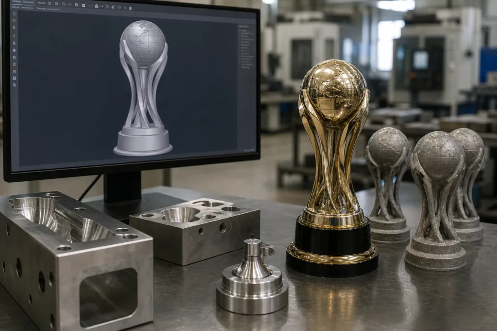
When a trophy has sculpted surfaces, hollow sections, multiple parts, or hidden fixings, a 3D trophy design file is often the most reliable way to communicate intent. A 3D model helps engineering check proportions, confirm how parts meet, and spot geometry that may be difficult to cast, machine, polish, or assemble. It also helps the factory decide whether the concept belongs in casting, die-casting, machining, or a hybrid process.
If the design depends on cast metal forms, undercuts, thin standing sections, or layered assembly, review the manufacturer’s metal casting capabilities before freezing the model. A shape that looks excellent in rendering may still need practical changes to support release, surface finishing, or stable assembly. That is why geometry review should happen before tooling, not after the first sample reveals a problem.
For 2D profile transfer, CNC contours, or flat pattern exchange, DXF is still widely used in manufacturing workflows. Autodesk describes DXF as a tagged representation of drawing data and a common interchange format, which is why it remains useful when the factory needs a clean profile from a drawing or cut path. For full 3D exchange, the safest approach is to send the native model plus a neutral export if the engineering team requests it.
A practical trophy CAD package should answer these questions:
- Is the shape a single body or an assembly of several parts?
- Which faces are cosmetic and which faces are hidden or structural?
- Where are the part lines, insert points, fixings, or magnets?
- Which areas must stay open for personalization, plating, masking, or polishing?
- Are there hollow sections, ribs, or wall changes that must be reviewed before tooling?
Do not guess at achievable thickness, release angle, or fit. Those limits must be confirmed by engineering for the specific project, material route, and finish plan. The purpose of a 3D file is to remove ambiguity, not to replace the factory’s review.
Personalization and Variable-Data Files
Personalization often creates more production risk than the main trophy shape because the base design may be fixed while the names, titles, scores, dates, or serial numbers change from one unit to the next. For this reason, variable-data files should be separated from the main artwork package and clearly labeled as editable, approved, or final.
The best practice is to supply one master list in spreadsheet form and one proof for layout. The list should show exactly how the text will appear on the product, including spelling, capitalization, punctuation, accents, line breaks, and any ranking order. If the project uses multiple languages, confirm the character set and proofreading process before release.
Useful fields for a variable-data sheet include:
- Item or award ID
- Recipient name or team name
- Title or category
- Event date or season
- Font size or layout rule if it is fixed by the brand
- Notes for special characters, abbreviations, or line wrapping
Ask for a layout proof whenever the personalization sits on a curved surface, a narrow plate, a small base, or a high-contrast finish. In those cases, line breaks and spacing are not just design issues; they affect legibility, production time, and final approval risk.
File Version Control and Pre-Tooling Approval Checklist
Version control sounds administrative, but it is one of the fastest ways to prevent mistakes. A project can move from concept to production in a few days, and if different teams are editing different files, the factory may receive a logo from one version, dimensions from another, and personalization from a third. That is how avoidable delays begin.
Use a naming system that shows the project name, revision number, and approval status. Keep one master contact who can confirm which file is final. If the project has a formal upload path, send the controlled package through the upload design files page instead of scattering attachments across email threads. That keeps the record cleaner for both buyers and engineering.
Before tooling, confirm the following:
- The approved logo or artwork file is vector where possible.
- All dimensions are clear and units are stated.
- The 3D model or profile reflects the latest revision.
- Personalization data matches the approved proof list.
- Color, finish, and plating references are locked or clearly marked for confirmation.
- Part assembly, packaging, and handling notes are included.
- The approval contact has signed off on the exact revision being used for tooling.
A controlled approval step is not a delay. It is the point where the project stops being an idea and becomes a buildable order.
Common File Problems That Slow Down Custom Trophy Production
Most production delays are caused by a small set of repeat issues. The file may look complete to a designer, but the factory cannot quote or tool with confidence until the missing details are resolved.
| Problem | Why it slows production | Better practice |
|---|---|---|
| Low-resolution logo image | Edges look soft and cannot be scaled cleanly | Send vector artwork or a rebuildable master |
| No scale or dimensions | The team cannot confirm the real product size | Add overall measurements and critical details |
| Several versions with no revision note | Engineering may quote or tool the wrong file | Mark one controlled approval version |
| Flattened image used as final art | Text and shapes cannot be separated for production | Provide editable layers or source vector files |
| Mixed unit systems | Creates fit and scale confusion | State one unit system clearly |
| Variable names embedded in the design only | Hard to manage repeated personalization | Supply a separate approved data list |
| Unconfirmed finish callouts | Polishing, plating, paint, and masking plans may differ | Note the intended finish and confirm any open points |
| No assembly logic | Factory cannot verify how the trophy will lock together | Show exploded views or assembly notes |
These are not small housekeeping issues. Each one can add extra rounds of clarification, which means the project spends more time in review and less time in production.
What to Send First: A Practical Handoff Checklist for Buyers and Designers
If you are preparing the first package for a custom award, send the information in the order the factory needs it. That helps the engineering team sort feasibility before it spends time on polish or presentation details.
- A short brief that explains the award purpose, audience, and desired look.
- The main logo or artwork file in vector form if available.
- One or more reference images that show the style direction.
- Approximate size range and the intended use case.
- Any 2D drawing with dimensions, or a clear sketch if a drawing is not ready yet.
- A 3D CAD model if the trophy has sculpted geometry, hidden fittings, or multiple parts.
- Personalization data, if names, titles, scores, or serial numbers are part of the order.
- Finish notes, packaging notes, and any brand restrictions that affect the build.
If the package is incomplete, say what is still in progress. A clear note such as pending font approval or pending recipient list is more useful than sending an unfinished file as if it were final. Good handoff discipline saves time on both sides.
When to Request Custom Trophy Design Services During Artwork Review and Feasibility Evaluation
Request design support when the concept is strong but the production path is not yet stable. That is usually the right moment to bridge creative work and factory reality. If the logo is not editable, the geometry is difficult to manufacture, or the assembly method is still uncertain, the project should move into structured review before tooling begins.
This is also the right time to ask for the mold development perspective. If the design requires a part split, internal support, hidden fixing, or finish protection in a tight area, mold planning should happen while the artwork is still flexible. Once the design is approved, changes become more expensive and slower to absorb.
A practical rule is simple: if the file answers only the visual question, it is not ready for manufacturing. If it answers visual, dimensional, personalization, and assembly questions, it is much closer to tooling readiness. For buyers managing complex programs across events, brands, or regions, the safest path is to bring engineering into the review early and keep the approved file set under control from that point forward.
When the project is ready for the next step, return to the custom trophy design workflow with the final artwork, controlled dimensions, and confirmed production intent. That gives the factory a cleaner handoff and reduces the chance of sampling loops later.
FAQs
What file format is best for a trophy logo?
Vector files are usually best because they scale cleanly and support production edits. AI, EPS, SVG, and editable PDF files are common starting points when the logo is truly vector.
Do I need a vector file if I already have a high-resolution image?
High-resolution images help as references, but they do not replace vector artwork when the factory needs crisp edges, engraving paths, or separate editable elements. A raster image may still need to be rebuilt.
What should a 2D drawing show before quotation?
The drawing should show overall dimensions, key views, logo placement, base size, and any details that affect assembly or finish. It should also state the unit system and identify the current revision.
When is a 3D CAD file necessary?
A 3D CAD file is especially useful when the trophy has sculpted surfaces, hollow areas, hidden fixings, or multiple parts. It helps engineering check geometry, assembly, and manufacturability before tooling.
What should be approved before tooling starts?
The final logo, dimensions, revision-controlled model or drawing, personalization data, and finish notes should all be approved before tooling starts. Any open technical point should be confirmed with engineering first.