
A disciplined die cast trophy sample review should answer a production question, not just an aesthetic one: is this sample truly representative of what mass production can repeat? For buyers sourcing die-cast metal trophies, the sample stage is where approval risk becomes visible across geometry, raw casting quality, secondary processing, finish consistency, assembly performance, and packaging fit. A trophy that looks acceptable in photos can still fail later because of hidden porosity, unstable assembly interfaces, inaccessible polishing areas, weak masking transitions, or poor carton protection.
That is why technical buyers, designers, and QA teams should treat sample review as a stage-gate exercise. The objective is to establish an approved production reference, often documented as a trophy golden sample, while clearly recording any concessions, pending corrections, or items that still require engineering confirmation. Project-specific tolerances, validation criteria, lead times, test standards, and acceptance thresholds should be confirmed for the specific program rather than assumed.
Confirm the Sample Stage and What It Can Prove
Before approving anything, ask a simple procurement question: what sample stage is this? Approval authority should depend on the answer.
Common sample stages and what they validate
- Visual prototype: used to review styling direction, relative proportions, and logo placement. It does not prove die-casting feasibility, tool split behavior, or production finishing consistency.
- CNC appearance model: useful for checking geometry and presentation, especially on machined surfaces, but it does not reveal authentic casting marks, draft effects, gate positions, or ejector evidence.
- Hand-made mock-up: useful for concept communication or event sign-off. It should not be treated as manufacturing evidence because finishing and assembly routes may differ from production.
- Pilot die-cast sample: starts to show real casting behavior such as parting, gate trimming, local mismatch, and relief reproduction. It can validate early manufacturability but may still come from trial conditions.
- Production-tool sample: the most relevant stage for manufacturability review because it reflects actual tooling, expected draft, ejection, trimming logic, and likely process limitations.
- Finished pre-production sample: used to judge how casting, polishing, plating, paint, logos, and assembly perform together in a production-representative flow.
- Golden sample: the approved master reference archived for production, incoming QC alignment, repeat orders, and dispute prevention.
In practice, a sample can validate only what its process history supports. If a buyer is reviewing a display model, they should not approve raw casting acceptability. If they are reviewing an unfinished casting, they should not sign off final metallic color or paint boundary quality. If they are reviewing a single hand-finished piece, they should be cautious about assuming repeatability across a bulk order.
For a robust die casting sample checklist, request the control documents at the same time as the sample:
- Latest drawing revision or approved 3D data
- Bill of materials
- Finish specification and color callouts
- Artwork or logo file revision
- Assembly instruction reference
- Packaging specification or pack-out sketch
- Sample deviation list showing known gaps from target production condition
Where a project requires staged evaluation, Me Trophy can support sample production discussions around what each sample can and cannot prove, so approval decisions remain aligned with tooling maturity.
Review Geometry, Parting, Gates, and Ejection Evidence

Once the sample stage is confirmed, move to raw geometry and process evidence. This step matters because visual finishing can temporarily hide issues that later reappear in production.
Start with the approved drawing or 3D data and inspect the overall silhouette, thickness transitions, edge definition, symmetry, relief depth, and any design-critical contours. Look for areas where thin-to-thick transitions may encourage sink, where deep relief may trap polishing media, or where a decorative edge may be softened by necessary draft.
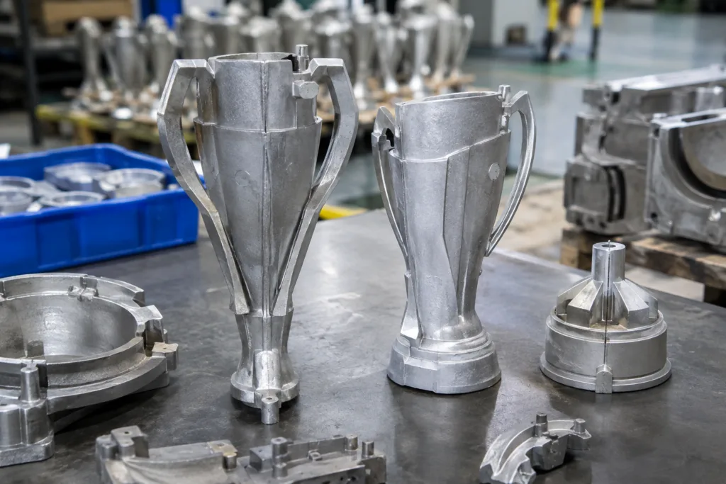
A true production-representative die-cast sample should show manufacturing evidence. Review parting lines and ejector marks, gate vestige locations, overflow cleanup zones, vent trimming areas, and local draft-related geometry changes. These features are not automatically defects; they are proof of process reality. The question is whether they are controlled, concealed, or aesthetically acceptable on the approved design. Buyers who need a deeper framework can review Me Trophy guidance on parting lines and ejector marks.
Pay special attention to gate removal and trimming. If a gate lands near a highlight edge, logo face, or narrow stem area, cleanup may reduce edge sharpness or create visible texture differences. Also check whether trimming leaves enough access for later grinding and polishing in recessed zones.
Raw casting inspection trophy sub-checklist
- Porosity visibility: visible pinholes, blisters after early polishing, or cavities in high-visibility zones
- Cold shuts: incomplete fusion lines, especially on thin decorative details
- Short fill risk: weak edge formation, incomplete relief tips, or underfilled corners
- Flash: residual thin metal at parting or vent areas beyond planned cleanup
- Deformation: bent stems, twisted panels, or local collapse after ejection
- Burrs: hazardous or visually obvious sharp remnants after trimming
- Warpage: base contact instability, misalignment, or curvature in long spans
- Surface pits after cleanup: defects exposed only once trimming or pre-polish work begins
This review should use recognized defect language rather than subjective comments such as “looks rough.” The North American Die Casting Association provides a useful reference point for industry die-casting standards for reviewing raw castings and sample acceptance, which can help teams frame findings consistently.
From a buyer’s perspective, not every issue has the same corrective path. Some findings are process-tunable, while others are likely tooling-related:
- Often process-tunable: minor flash, local trimming quality, some polishing-access issues, handling marks, or isolated finish contamination
- May require tool rework: persistent mismatch, incorrect relief depth, unacceptable parting placement, recurring short-fill tendency, problematic ejector positions, or geometry that cannot be cleaned without damaging the design intent
If a defect can be removed only by over-grinding or over-polishing, it is rarely just a cosmetic matter. It may indicate a deeper geometry or mold condition problem that should be addressed before final approval.
Measure Critical Dimensions and Assembly Interfaces
Not every dimension deserves equal approval weight. During a trophy pre production sample review, identify the features that directly affect fit, stability, and interchangeability, then classify them by function.
Priority dimensions to review
- Stem-to-base interface dimensions
- Screw holes, thread features, and pilot locations
- Locating bosses and alignment tabs
- Adhesive contact areas and seating surfaces
- Badge recesses, emblem pockets, and insert depths
- Nameplate zones and engraving panels
- Insert positions and any mating features between multiple metal parts
Compare measurements against the latest approved drawing revision and label them clearly in the review file:
- Critical-to-fit: affects assembly, upright positioning, repeatability, or part interchangeability
- Nominal reference: useful for process control but not necessarily a release blocker on its own
- Cosmetic reference only: matters for appearance but may be reviewable under visual approval criteria rather than strict dimensional release
Suitable measurement methods at sample stage may include calipers, height gauges, visual fit checks, basic fixtures, or go/no-go tools. For more complex geometry, coordinated dimensional verification may be appropriate, but the exact method should be confirmed by the project team. NIST provides a helpful reference on dimensional inspection best practices from a metrology authority, reinforcing the need for disciplined measurement systems when dimensions drive approval decisions.
For assembly interfaces, do not stop at single-point measurements. Build and inspect the sample as an assembly:
- Check alignment and perpendicularity between upright elements and base surfaces
- Confirm seating depth and whether gaps are visible from normal display angles
- Evaluate thread engagement and torque feel where applicable
- Verify adhesive coverage zones and whether bond surfaces are fully supported
- Check repeatability across more than one sample if multiple pieces are available
Dimensional deviation can sometimes be accepted by concession, but only if the concession is documented and does not create downstream risk. Typical concession candidates may include a hidden non-critical dimension or a cosmetic radius variation that does not change fit or visual intent. By contrast, tool correction or design revision is usually the better path where the deviation affects assembly stability, recurring orientation, visible gap control, or compatibility with standard fixtures and inserts.
Inspect Polishing, Plating, Paint, and Logo Details
Many approval mistakes happen because teams treat “finish” as one category. In reality, defects can originate from the casting substrate, grinding, polishing, plating, painting, printing, or final handling. Separating those sources improves corrective action speed.
Start by asking whether a visible issue existed before finishing. A pit that appears after plating may actually be substrate porosity. A rounded emblem edge may have come from over-polishing, not from mold definition loss. A contaminated paint line may be a masking or cleaning issue rather than a color problem. Me Trophy’s manufacturing review should therefore align finish checks with broader quality control checkpoints across the full process route.
Polishing review points
- Edge preservation versus over-polish rounding
- Consistency on highlight faces and broad reflective areas
- Scratch direction and whether linear marks remain visible after final polish
- Waviness or uneven metal removal on flat or gently curved surfaces
- Accessibility in recesses and behind raised features
Plating or metallic finish approval points
- Color consistency between components and across visible faces
- Gloss level and reflectivity under agreed lighting
- Coverage in recesses and around internal corners
- Edge build-up or loss of crispness on relief details
- Pitting visibility, burn marks, or local dull zones
- Peeling risk indicators such as poor adhesion appearance or unstable edges
- Clean transitions between masked and unmasked areas
For die cast finish approval, review under controlled lighting and agreed visual conditions. If the project uses a special metallic standard, paint code, accelerated corrosion requirement, or salt-spray target, those criteria should be confirmed for the project and included in the specification package rather than assumed from a prior order.
Paint and coated detail review points
- Color match method and reference standard used
- Coverage uniformity in recessed and exposed areas
- Overspray risk on metallic edges or polished highlights
- Boundary sharpness at masked transitions
- Paint pooling, thin spots, or weak edge coverage on chip-prone corners
Logo and artwork review points
- Relief clarity and engraving depth
- Printed registration and orientation
- Small text legibility
- Emblem placement and centering
- Branding direction relative to front-view presentation
When logo application and component joining happen late in the route, it is useful to review them together because handling damage can occur between decoration and final build. That is especially true for programs involving secondary badges, engraved plates, or multiple assembled metal parts, where engraving and assembly quality should be judged as a combined release condition rather than separate approvals.
Check Stability, Function, and Packaging Fit

A visually attractive sample still fails if it rocks on the table, loosens in transit, or abrades inside the carton. Functional approval should therefore cover standing performance, fastening security, and pack-out protection.
Begin with physical stability. Place the assembled trophy on a flat reference surface and confirm that it stands level, that the center of gravity is appropriate for normal display handling, and that the base does not rock. If the trophy includes a tall upright, asymmetrical design, or stacked assembly, check whether slight process variation could increase lean risk in production.
Then review any functional features:
- Removable elements and whether they locate positively
- Nameplate areas and fit of decorative inserts
- Fastening systems such as screws, threaded studs, or concealed hardware
- Interchangeable badges or modular award components
Assembly security should be judged both visually and tactically. Look for looseness, unwanted rotation, rattle, adhesive squeeze-out, exposed fasteners, and final handling marks. If multiple samples are available, compare repeatability rather than assuming one good unit proves the process.
Packaging review at sample stage should go beyond “it fits in the box.” Confirm whether the insert or tray actually prevents movement, whether protective film or bagging prevents metal-to-metal abrasion, whether the orientation is obvious for packers, and whether carton labeling fields are defined. For export programs, outer carton construction, drop performance expectations, humidity exposure risks, and logistics labeling requirements should be confirmed project by project. Buyers planning global shipments should evaluate both presentation and transport protection together, especially where a supplier supports packaging and export delivery.
Near final release, it is also wise to revisit the commercial decision point with the product family page for die-cast metal trophies, so the approved sample aligns with the intended manufacturing route, finish package, and assembly architecture before PO scale-up.
Create the Approved Master and Deviation Log
Once the sample is acceptable, the next task is to convert it into a controlled production reference. This is where a reviewed sample becomes a trophy golden sample and approved master.
The approved master should not be just one physical piece on a shelf. It should be supported by a revision-controlled document package so procurement, engineering, manufacturing, and QA are all using the same release baseline.
What should be archived
- Signed or acknowledged sample photos from agreed viewing angles
- Revision-controlled drawing and, where applicable, approved 3D reference
- BOM and assembly breakdown
- Finish callouts, color references, plating notes, and logo files
- Approved packaging method and pack-out orientation
- Inspection checklist used during approval
- Deviation log with open and closed items clearly marked
Recommended deviation log structure
- Issue description
- Location on part or assembly
- Severity
- Temporary acceptance status
- Owner
- Corrective action path
- Tool rework required: yes or no
This handoff is critical. Buyer and manufacturer should both understand what is fully approved, what is conditionally approved, what remains under engineering change, and what cannot yet be considered mass-production representative. For example, a sample may be approved for geometry but not final plating tone, or approved for pack-out direction while a cavity correction is still pending.
Stage-gate sample checklist summary
| Stage gate | Approval focus | Release question |
|---|---|---|
| Geometry approval | Silhouette, relief, symmetry, draft impact, manufacturable form | Does the tool-created part match approved design intent closely enough for production? |
| Raw-casting approval | Porosity, cold shuts, flash, gate trimming, ejection evidence, mismatch | Is the casting sound and controllable without destructive cleanup? |
| Secondary-operation approval | Grinding, trimming, drilling, tapping, fit features | Can secondary processing create repeatable assembly-ready parts? |
| Finish approval | Polish, plating, paint, logo clarity, masked transitions | Does final appearance remain consistent with substrate reality and spec intent? |
| Assembly approval | Alignment, fastening, adhesive control, stability, handling marks | Can the product be assembled securely and repeatably? |
| Pack-out approval | Protection, orientation, abrasion prevention, presentation | Will packaging protect and present the approved build condition? |
An effective approval handoff protects future repeat orders as much as the first production run. If a condition is not documented, it is difficult to enforce later.
Conclusion
An effective die cast trophy sample review separates casting reality from finish appearance, verifies what each sample stage can actually prove, and records every approved condition before scale-up. That means checking geometry, raw casting evidence, critical dimensions, finish behavior, assembly performance, and packaging fit as linked gates rather than isolated observations.
For technical buyers, product designers, and QA teams, the safest path is a formal checklist, a controlled deviation log, and an approved golden-sample record. When working with a manufacturing partner such as Me Trophy on die-cast metal trophy projects, that discipline helps ensure the final release reflects real production capability rather than a one-off presentation piece.
Frequently Asked Questions
1. What is the difference between a visual prototype and a production-tool sample?
A visual prototype mainly validates appearance, proportions, and concept direction. A production-tool sample is made through the intended die-casting route and can reveal parting lines, gate vestiges, ejector evidence, trimming effects, and production-related geometry behavior. Approval authority should be much higher for the production-tool sample.
2. What should a die casting sample checklist include for trophy approval?
It should include sample-stage confirmation, drawing revision review, raw casting inspection, critical dimensions, assembly interfaces, polishing and plating evaluation, paint and logo checks, stability testing, packaging fit, and a documented deviation list. Project-specific tolerances and acceptance criteria should be confirmed before final sign-off.
3. When does a raw casting issue require tool rework instead of cosmetic cleanup?
If the issue is recurring and tied to geometry, mismatch, gate placement, ejector location, relief definition, or persistent fill behavior, tool rework may be necessary. If the issue is limited to minor removable flash or local cleanup quality, it may be process-tunable. The decision should be documented against the approved sample and drawing.
4. How should buyers approve die-cast finish appearance?
Finish approval should be done under agreed lighting and visual conditions, while separating substrate defects from polishing, plating, paint, and handling defects. Buyers should record approved photos, finish callouts, and any color or corrosion expectations that must be confirmed for the project.
5. What makes a trophy golden sample useful for future orders?
A golden sample becomes useful when it is tied to revision-controlled documents: signed photos, drawings, BOM, finish specification, packaging method, inspection checklist, and deviation log. Without that documentation, the physical sample alone may not protect repeatability across future production.